Griffin Effects
January 2009
RESISTORS:
Resistors restrict the flow of electric current. For example, we would put a resistor in series with an LED to reduce the amount of current flowing to the LED so it doesn't burn out. Resistors are not polarized (meaning they don't have a positive or negative) and can be connected either way. Resistors are measured in ohms. 1K equals 1000 ohms. Resistor values are normally indicated by colored bands. Most resistors have 4 or 5 bands. On a 4 band resistor, 3 bands indicate the value while the 4th band indicates the resistors tolerance (precision). On a 5 band resistor, 4 bands indicate the resistors value and the 5th band indicates the tolerance (precision).
Tolerance or precision is a percentage value. If a 10k ohm resistor has a 5% tolerance. The actual value can be 5% above or below 10k ohms. Typically in effects building we use metal film and carbon resistors usually in the 1/4 watt range. You could also use 1/8 watt resistors where space is limited and the voltage allows as they are typically smaller.
Metal film resistors are used where noise could be a problem as they are characteristically less noisy than the carbon composition. You can use them anywhere but in the signal path is where they are more useful. We aren't going to get into any "Mojo" debates. We are going to try to keep this simple and stick with the basics.
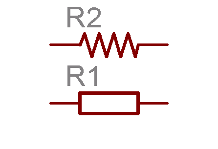
This is what a resistor usually looks like in a schematic. Either the zig-zag line or the rectangle.
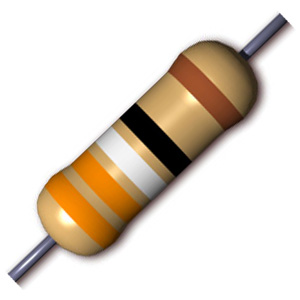
This is a 5 band resistor. On this one the 4 grouped stripes indicate the value and the separated brown stripe indicates the tolerance.
Capacitors:
Capacitors are used to store charge. They function much like a rechargeable battery. A capacitors storing ability (capacitance) is measure in farads. 1 farad is a huge amount of charge so we usually measure capacitors in microfarads (uF), picofarads (pF) and nanofarads (nF). A capacitors voltage rating is very important. Use a capacitor that has a larger voltage rating than the amount of voltage the circuit supplies.
There are many types of capacitors. Again, we are going to try to avoid the mojo issue here. We are going to start off by talking about non-polarized and polarized capacitors.
Non-Polarized Capacitor:
A non-polarized capacitor doesn't have a positive or negative pole so it can be connected either way in a circuit.
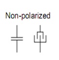
These are some schematic symbols of non-polarized capacitors.
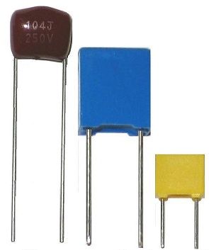
These are some non-polarized capacitors
Polarized Capacitor:
A polarized capacitor does have a positive and negative pole. If inserted into a circuit the wrong way, it usually won't work. Polarized capacitors will either have their negative or positive leg marked on the capacitors casing.
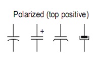
Here are some schematic symbols for polarized capacitors.
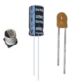
Here are a few polarized capacitors. The orange tantalum capacitors positive leg is marked with a + sign on the capacitors case. The black aluminum electrolytic capacitor has it's negative leg marked with the grey stripe down the side and the SMT cap has a black mark on the top edge denoting the negative side.
Hope this helps in understanding a little about resistors and capacitors